Hi Ian,
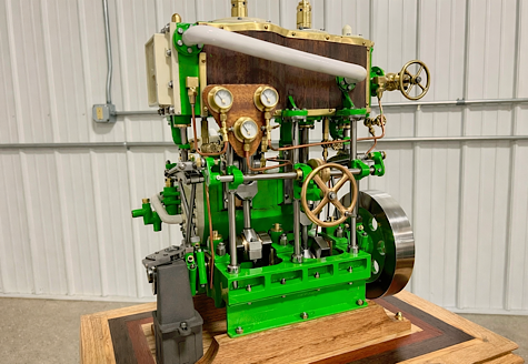
With the small scale of the engine I was limited to how small I could make the gear on the governor and still maintain the center spacing so the gear on the crank is 17 teeth and the gear on the governor is 14 teeth so the ration is just around 1.25:1. Not a great increase but a little faster. In the video when I increased the engine speed the engine is running on the governor. This is with about 20 psi. It will run on only a couple of pounds but it won't get up to governed speed. When using governors on these miniature engines the governor has to overcome the friction of all the links and valves which no matter how small they are the balls will fly out it's when the speed is brought back down that the weight of the balls isn't enough to bring the governor back to rest. On this one I added a .06 I.D. spring wound from .008 music wire. I kept stretching it out until it worked in both directions, flying out and returning. It's a fine line on something this small.
gbritnell
As a side note I had mentioned about the spread sheets that a contributor to one of the other forums had created. I opened up the sheet and kept plugging numbers in, D.P. and tooth count until I came up with the final numbers that would meet the center to center spacing. I needed to maintain this because I had already machined the entablature for the crankshaft and governor pocket. In hind sight I should have done my gear calculations prior to machining the governor pocket then I could have probably got the governor to spin a little faster.