It appears that the Red Frame portion of the Solar 1 engine may offer the best easy visual guide to which era an engine truly represents, in the early years of production.
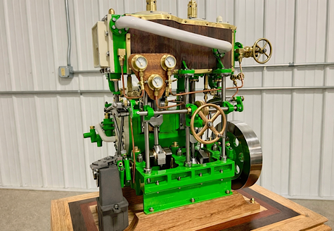
[ Guests cannot view attachments ]
Type 1 frame; If you will note that in the photo above, the engine frame farthest away is the Davies Charlton Hot Air Engine Frame.
Type 2 frame; The frame in the middle is numbered in the 56xx range, and is from an engine with a Thermal Energy Engines - Phoenix Arizona, and also found with Phoenix Arizona - Solar Engines without an R (in circle), marked bases.
Type 3 frame; While the bottom frame is representative of everything produced more recently than that, including Phoenix Arizona - Solar Engines with an R (in circle) and Made In USA - Solar Engines with an R (in circle)= PM Research, Wellsville, NY.
Notable similarities and differences:
1.) The DC frame is cast in a mold showing very little if any pressure injection, is rife with flaws commonly associated with low grade pot metals, such as sink, shrink and fractures to the point of crumbling. It is made of a rather heavy alloy that likely has some fair percentage of Lead and Zinc, but is probably lacking much in the way of Tin, as that would have tended to allow for better performance. Just guesses as to composition really, but somewhat educated guess for all that. Likely, this one's frame flaws is an anomaly, and not representative of overall production, but the process and materials are clearly marginal, even when they more typically produce better parts. There are no ejector pin marks evident on this frame, which again speaks to a low pressure, likely gravity feed, molding process, that may better be described as enclosed casting. While the flywheel bearing "ears" are prominently buttressed on the outside surface, the inside is just a straight wall. The engine mount surface is 1.00" above the base and has two small holes, possibly molded in that accepted self-tapping 5-48 screws about 1/2" long, and just 1" apart. The holes for the flywheel axle bearings are .312" diameter located 1.110 above the frames base. The holes in the bottom of the frame for mounting to the base plate are also sized for self-tapping 5-48 screws, spaced along the center-line of the frame 2.5" apart starting about 5/16th of an inch from the axle end of the frame.
2.) The TEE frame shows marked evidence of superior materials and process, showing a perfectly filled surface without any signs of sink, shrink or structural flaws. There are now apparent, four pronounced ejector pin marks on the reinforcement ribs which form an "X" in the inside bottom of the frame, strongly suggesting transition to an actual closed pressure injection process, using superior alloys that are much stronger, lighter in weight and more cohesively packed out, better filling the mold. Oddly, while the engine mount surface remains 1.00" above the base, with the same mount hole spacing, the "ears" are now a bit lower, with the center-line of the flywheel axle just 1.070" above the base, probably caused by a determination that with the new materials and process the base of the frame didn't need to be so thick anymore, which turned out to be a mistake requiring shims be placed under the frame to lift it off the base far enough to clear the flywheels, whose diameters had been increased as well, but more on that later. The screw holes in the bottom of the frame for mounting to the base plate are also still at 2.5" spacing, but start about 1/8" further from the axle end of the frame, though some variance is noted, suggesting that these holes or pilots for them are not molded in, but rather drilled and tapped (6-32) in a second operation, likely fixture controlled, but often those fixtures allow for some deviation in set-up.
3.) The final frame configuration offers all of the upgrades featured in the previous listing, and the same mount hole sizes and spacing's, but corrected the too low height of the flywheel axle bearing holes so that shims would no longer be required for flywheel clearance on the base. A feature that was added at this time was an inner buttress to the ears, thus slightly thickening the ears, the draft of which suggests that the cavity in the mold was deepened using an EDM process. This inner buttress is a key diagnostic for this latest generation of frames.
Note:
There are some exceptions to these observations so far noted, that will be dealt with in a follow up post.