More tinkerings. Replacement cross feed drive came today. It's wired incorrectly, such that it works in reverse. Will open it up and sort that at some point. Not a big deal, plus it was CHEEEEEP.

More importantly, I flattened the underside of the base casting. Levelled it first longitudinally along the regions I had given a light sanding on the surface plate. Crosswise it was about 0.007" off, which I figured was not enough to worry about, and in any cae with this set up I'm levelling the base relative to the (admittedly unfinished) slide rails. Seems like as good an approach as any.

Took off about 15 thou.

Still a couple of rough spots, but I don't think it's essential to take those out, I just want a good level surface around the whole perimeter.
Then set it up on my flattened aluminium fixture plate. Set it up so that it was as square as possible to the aluminium plate, using the slide rails and cylinder mounting face as references, as best as possible since they are not machined. Essentially "averaged" the position between the 3 surfaces, which should work well when I start cleaning material.

Yes, I did support under the extremes of the casting.

Then went around and drilled through the bosses, lightly spotting in to the plate below. Then removed the casting, tap drilled the plate, and tapped the holes to 4-40 thread.
Hey presto, base casting now on a holding plate and ready for machining.

I need to take a file to some of the flash first, but then I will look at setting up to machine the datum face where the cylinder mounts, once I have written out my operation sequence.
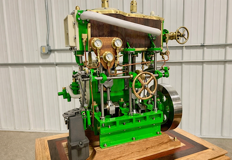
I decided to make a start on the base today.
I decided to start with cleaning up the end face. This is the datum surface everything is referenced from. My plan being to get this flat, then put all the holes in it, and use the center hole to locate the height of the slide rails, and also establish the center line for cleaning up the insides of the rails and the inner surfaces of the bearings for the crankshaft.

Although the drawing calls for spotfacing the end, that seems unnecessarily complicated to achieve - I suppose not much work with a boring head - but just milling it flat over a large enough area is simpler at this stage.


Then mounted it upright for the end face. I saw someone else mount one a bit like this, but I was concerned about how the plate would actually hold up. Thought I'd try it though.

I did mark up the end as a visual aid. I like to establish points from edges using an edge finder, and then center drill locations, rather than try center punching them. But I thought it might be a good sanity check to have this marked out to refer to.

Worked out OK. I actually found center by measuring the part, and then using an edge finder, and indexing from there, to keep the center point central, but my back up scribing was reassuring to have.

However, the plate did start to vibrate, so I decided to remount before going further.
I have this angle plate. I crudely set it up first


Then secured the fixture plate to the angle plate, and used the actual part face to get everything squared up, level and true.

I found center of the part again, using a co-axaial indicator, and then started spotting holes.

I used the geometry approach to establish the coordinates for the bolt circle pattern, which is very simple on a six hole pattern. My little Zeus book has these all predefined for easy reference.

Anyway, a bunch of counting of dial turns later, being sure to remember to take up backlash, and there we have it.

Test fit:


Which looks OK to me.
Then I spent a little time cleaning up the boss surface.


It seems to take me an exceptionally long time to set jobs up. For instance setting up the angle plate and getting the face of the base casting level and true was about 2 hours. But maybe that's just a matter of practice. At this stage I'm more interested in getting the set up right, than how long it takes to do it. I'm pleased with the last few workshop sessions results.